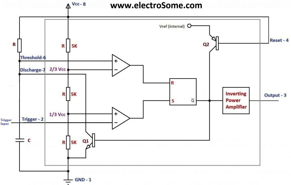
Schematic 555 Timer Circuit Diagram - How Can We Make A Timer Of 5 Minutes Using 555 Ic Timer Quora : Simple 555 timer circuits & projects.. The 555 timer ic is an integral part of electronics projects. As we know 555 timer ic is one of the commonly used ic among students and hobbyists. Here, we take a look at some 555 timer circuits based on the ic. We have seen in the last few tutorials that the 555 timer can be configured with externally connected components as multivibrators, oscillators and timers, with timing intervals ranging from a few microseconds to many hours. Figure 1 is the pinout and functional block diagram for the 555 timer ic.
We have seen in the last few tutorials that the 555 timer can be configured with externally connected components as multivibrators, oscillators and timers, with timing intervals ranging from a few microseconds to many hours. We have a large collection of simple and advanced projects using 555 timer ic. The 4rth circuit diagram shows the standard ic 555 adjustable timer circuit having two sets of timing ranges and an output relay for toggling the desired load. Its name is derived from three 5k ohm resistors ,connected in series used in it.the timer ic can produce required waveform accurately. The reset input current draw illustrates the need for a current limiting resistor as shown in some of the preceding circuits.
Monstable Multivibrator Using 555 Timer from electrosome.com The 555 ic timer circuit above shows a very straightforward design where the ic 555 forms the central controlling part of the circuit. The 555 timer ic is an integral part of electronics projects. The diagram also shows the connections for using the 555 as a basic monostable multivibrator or timer, and the following explanation assumes that the ic is connected in this configuration. Let us discuss in detail about this circuit. 555 one shot timer | circuit diagram. The 555 is also very versatile, and can be used. Supply voltage requirements range from 3 to 18 volts, making the 555 one of the most versatile integrated circuits available. 555 timer, as the name specified, are the electronics circuits used for measuring time intervals.in this article, we will cover about 555 timers.
Let us discuss in detail about this circuit.
555 timers are very popular in electronics. Contact less car door left open reminder alarm. 500ms is the same as saying 0.5s so by rearranging the formula above, we get the calculated value for the resistor, r as: The 4rth circuit diagram shows the standard ic 555 adjustable timer circuit having two sets of timing ranges and an output relay for toggling the desired load. With this information you will learn how how the 555 works and will have the experience to build some of the circuits below. This enables the 555 to operate as a window detector. A collection of 555 circuits using the 555 timer as an astable oscillator with different duty cycles. The next diagram shows the basic current consumption of 555 timer chips from different manufacturers. We have seen in the last few tutorials that the 555 timer can be configured with externally connected components as multivibrators, oscillators and timers, with timing intervals ranging from a few microseconds to many hours. Figure 1 is the pinout and functional block diagram for the 555 timer ic. 555 timer circuits the 555 timer is a simple integrated circuit (ic) that can be used in electronic circuits, projects, and a variety of applications like timer, pulse oscillator, delays, flip flop, etc. The ic can operate in three different modes such as astable, monotstable and bistable, because of which it can be adapted into many types of circuit designs like time delay circuits, pulse generation circuit, oscillator circuit and much more. The 555 timer ic is an integral part of electronics projects.
To rate of flashing lamp can be calculated as. With this information you will learn how how the 555 works and will have the experience to build some of the circuits below. As we know 555 timer ic is one of the commonly used ic among students and hobbyists. The following example shows the 555 timer in bistable mode. 555 timer was first introduced by signetics corporation in 1971 as se555/ne555.
Blink Two Leds Alternatively With 555 Ic Classic Ic Circuit Diagram Ii from thecustomizewindows.com The following example shows the 555 timer in bistable mode. For 5 min, 10 min and 15 min you just have to change the resistor value (r 1). Contact less car door left open reminder alarm. A collection of 555 circuits using the 555 timer as an astable oscillator with different duty cycles. We have seen in the last few tutorials that the 555 timer can be configured with externally connected components as multivibrators, oscillators and timers, with timing intervals ranging from a few microseconds to many hours. Here we have controlled the output frequency of the pwm signal by selecting resistor rv1 and capacitor c1. Working modes of 555 timer ic. The 555 timer is a simple integrated circuit that can be used to make many different electronic circuits.
We have a large collection of simple and advanced projects using 555 timer ic.
There are simple circuits for beginners and advanced engineers. After one minute of time duration, the led will automatically turn on. When the figure 4 timer circuit is in its quiescent state, pin 2 is held high via r4, q1 is saturated and forms a short across timing capacitor ct, and pin 3. Each mode of operation indicates a circuit diagram and its output. Adjustable on off timer(using 555 astable mode) in this circuit a timer with cyclic on off operations is designed. Supply voltage requirements range from 3 to 18 volts, making the 555 one of the most versatile integrated circuits available. The 555 timer is a simple integrated circuit that can be used to make many different electronic circuits. The 555 ic timer circuit above shows a very straightforward design where the ic 555 forms the central controlling part of the circuit. Resistive network consists of three equal resistors and acts as a voltage divider. 555 timer bistable example circuit. With this information you will learn how how the 555 works and will have the experience to build some of the circuits below. Some devices will not function properly if the current to the threshold input is not restricted. Here, we take a look at some 555 timer circuits based on the ic.
555 timer helpers schematic the addition of a capacitor to the trigger will not work for short output pulses as there The diagram also shows the connections for using the 555 as a basic monostable multivibrator or timer, and the following explanation assumes that the ic is connected in this configuration. The speed at which the led (d1) is turned on and off is set by the values of r1 and r2. To rate of flashing lamp can be calculated as. 555 timer was first introduced by signetics corporation in 1971 as se555/ne555.
Use A 555 Timer As A Switch Mode Power Supply Edn from www.edn.com This is a 555 one shot timer circuit. The 555 ic timer circuit above shows a very straightforward design where the ic 555 forms the central controlling part of the circuit. With this information you will learn how how the 555 works and will have the experience to build some of the circuits below. Each mode of operation indicates a circuit diagram and its output. Once this switch is pushed, the circuit pulls its output to a. Contact less car door left open reminder alarm. Daman shah june 5, 2021. You can for example use it to reverse the direction of a robot when it bumps into a wall.
555 timer was first introduced by signetics corporation in 1971 as se555/ne555.
A monostable 555 timer is required to produce a time delay within a circuit. The circuit will not repeat it's timing cycle if the push switch s1 will remain on or pressed, after a timing cycle is completed. Schematic video this video walks you through building this circuit using a breadboard. Using the 555 timer ic in special or unusual circuits. 555 timers are very popular in electronics. 555 timer is an industrial standard ic existing from early days of ic. Let us discuss in detail about this circuit. Ton = 0.69*(r1 + r2)*c | toff = 0.69*r2*c This integrated circuit can be used in a variety of ways from which the basic one is to produce accurate and stable delays in electronic circuits.additionally, it is available in 8 pin dip and 14 pin dip. The 555 timer is a simple integrated circuit that can be used to make many different electronic circuits. 555 datasheet 555 duty cycle 555 metronome 555 reset function 555 time delay relay inverted 555 timer pulse generator. With this information you will learn how how the 555 works and will have the experience to build some of the circuits below. 555 timer pwm generator circuit diagram and explanation:
Resistive network consists of three equal resistors and acts as a voltage divider 555 timer schematic. After one minute of time duration, the led will automatically turn on.


0 Komentar